This article was originally published in NSR 103 September/October 2017.
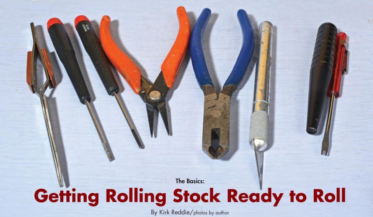
Rolling stock is always a favorite aspect of model railroading. Many collect rolling stock based on their interests, or because they enjoy collecting. Others develop a strategy for acquiring equipment based on their layout planning. As time goes on, many modelers enjoy upgrading their fleet with newer versions of models, while others enjoy the challenge of making an older model feel more prototypical through detailing and/or repainting. Regardless of preferences and goals, it is good to have certain tools and understand some of the options that are available to ensure maximum enjoyment of the equipment. The following figures discuss some hopefully useful tips in working with rolling stock.Above. Useful tools include, left to right: a tweezers, slot screw-driver, Philips screw-driver, needle nose pliers, diagonal cutters, X-Acto knife, an Aztec bolster pin pusher (exotic but it is actually quite useful!), and… I have no idea what this is called but it is a slot screwdriver with a slit cut in it that makes it useful to remove friction-fit bolster pins.
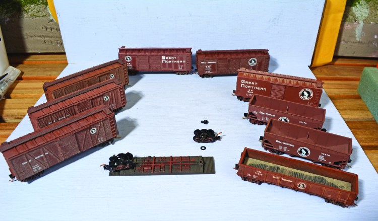
Above. If one is inclined, a first step might be to acquire equipment that fits the era and geography. Many of us want to interchange with railroads we don’t have time to research so we tend to acquire factory-decorated models. Somewhere I have Hank Stevens’ book on GN freight cars that explains colors and lettering. I know I want to avoid the bright red, jade green, and big sky blue schemes. Most GN cars were brown in my era with some orange/green plywood sheathed cars, a few Pullman green express boxcars, and a few cars in Empire Builder colors. For Pennsylvania RR cars I embargo the shadow-Keystone and look for circle-Keystone and earlier logos. On the Milwaukee Road, I embargo most cars with “The Milwaukee Road” logos and look for “CMStP&P” logos. These choices are based on my historic modeling point of about 1950. Having perfect rolling stock is a whole hobby unto itself, so I just go for what I think looks correct.
Truck- or Body-Mounted Couplers?
Everyone has their own tastes. I model circa 1950 and keep things simple by using 1973 technology with Micro-Trains deep “pizza cutter” flanges and truck-mounted “talgo” couplers. The alternative is smaller flanges on wheels which usually means more weight and body-mounted couplers that are fussier to operate correctly. (One of the first things I noticed when I switched from H0 to N is that the truck-mounted Kadee/Micro-Trains and the Rapido couplers always worked.) Regardless of choice, it is probably better not to mix systems, and it is good to troubleshoot before operating.
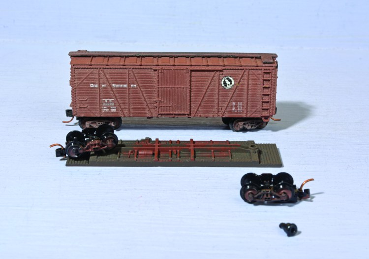
Above. New tooling is great but a lot of the old tooling cars are still usable. One of my finds are the ancient Bachmann composite single sheathed boxcars. They don’t resemble any Milwaukee cars I am aware of, but the factory Great Northern looks great to me. I add MT-1000 trucks and couplers and often a Micro-Trains (MTL) “wood” running board.
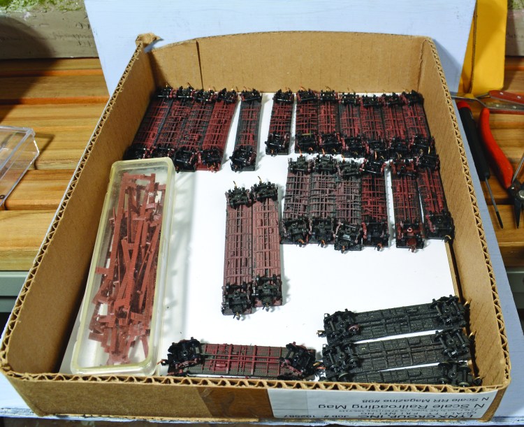
Above. Many of the old cars, except Micro-Trains and Con-Cor, use the same size bases. I change most freight car trucks to Micro-Trains MT-1000s and paint the outside boxcar red. It is more efficient to do a batch ahead of time and just change out the bases.
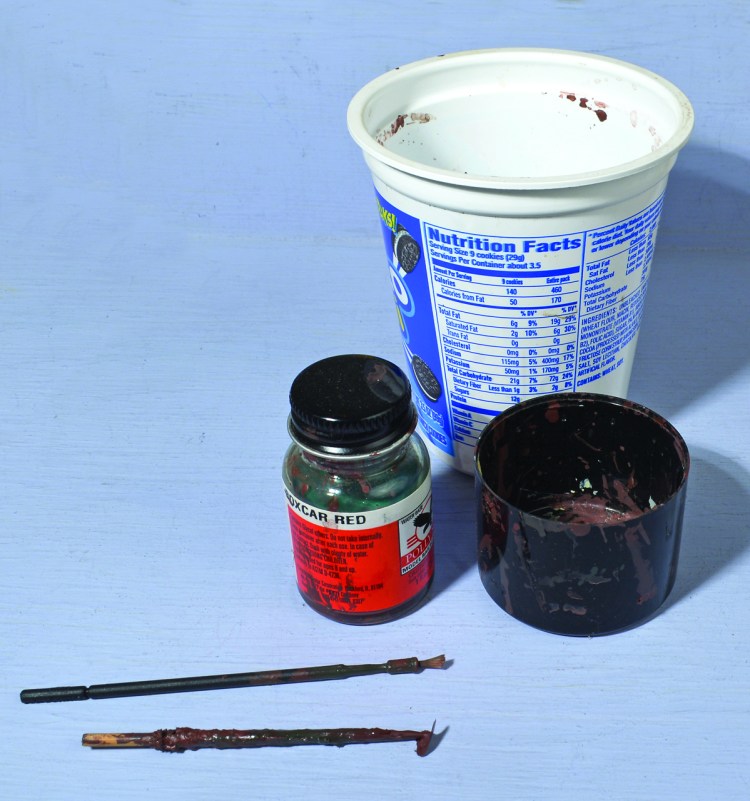
I have an arsenal of Polly Scale Boxcar Red that is no longer available but there has to be a substitute. I use a cut off wood skewer to stir the jar and dip the micro brush on the skewer to gather the paint. I paint the outside of the truck and the face of the wheel. Do not paint the needle bearing, flange, or tread as that will exaggerate their oversized appearance and could cause rolling problems on the track.
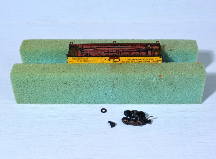
Above. I gathered a small fleet of foam cradles to work on rolling stock. They are useful for painting and decaling as well as changing trucks.
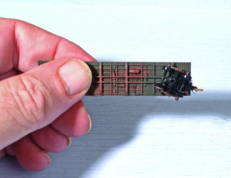
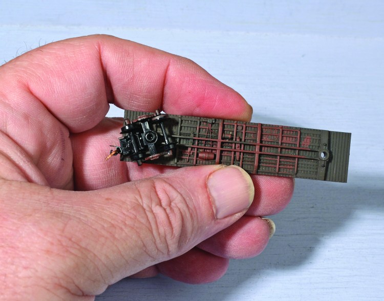
Above (2). When using Micro-Trains Line truck-mounted couplers, the coupler height is always correct. With body-mounted couplers one can check this with a gauge or an MTL1000 truck and coupler. Another important thing to do when preparing a car for operating is to make sure that the trucks swing freely. This is easy to check with truck-mounted couplers. If the pin is too tight the truck won’t freely swivel. If it is too loose, it will fall off. If the pin is too loose, I use a needle nose pliers to pinch the pin a bit. Note in Figure 8 the bolster (mounting point on the right side of the underframe) has a couple nubs. These are designed to stabilize the truck. Often they will be on only one end of the car. This end should have the truck mounted with a bit less wobble than the other end. It helps the car ride better on the track.
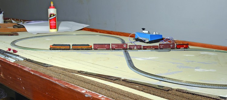
Above. Unless you desire to simply display your rolling stock, there is no substitute for being able to run your equipment. If time and space are a limitation, building a test track is a good idea. The goal of a test track is to identify equipment deficiencies that would cause a failure on a real layout. I originally planned to have cosmetic 78-inch radius with a standard of 22 inch minimums on my permanent layout, but greed took over and I have some tighter sections with Kato 12 3/8-inch radius curves.
We want to test the cars turning both left and right to check free swiveling of the trucks and free rolling of the axles. The 90-degree crossing and re-railer helps to find wheels that may not be firmly inside their trucks and metal wheels that are out of gauge. A Micro-Trains gauging tool is useful here as well. It will provide a couple height standard and can be used to determine whether wheels are in gauge. MT wheels are cast to be uniform, but some wheels, including many metal ones can move on the axle.
The figure-eight trackage shown above makes an excellent test track. I put it on my future Tacoma Tide Flat yard site. I plan to mount it on a 64 inch x 28 inch platform to test everything that will run on my layout. Prototype railroads were methodical about these things and it is something that all operating model railroads should emulate. I encourage you to run your equipment, and a bit of quick testing will make that more fun.
Formula for 12 3/8-inch radius figure 8
The minimum trackage requirement using Kato Unitrack:
Item: Quantity:
Kato no. 20-120 12 3/8″/R315 curve track 12
Kato no. 20-320 90° degree crossing and 4 small tracks 1
Kato no. 20-000 9.76″ /248mm straight track 2
Kato no. 20-041 feeder track 2
Kato no. 20-010 7.32″ /186mm straight track 1
Kato no. 20-021 re-railer 1
Kato no. 20-040 2.44″ straight track 1
Kato Power Pack
Note: Additional straight tracks can be added to lengthen the run of the loops if space permits. This test track could become the basis for a first layout as well, and switches (turnouts) and sidings can be added.
Return to Resources for Beginners